


Ford 7.3 Install Guide
Insane Diesel Installation Guide
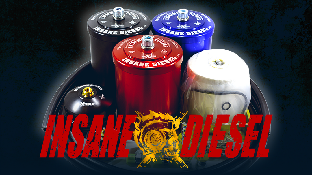
Ford 7.3L Diesel Bypass Oil Filter Frame Mount Kit Installation Guide
Fitment Notice
This guide applies to the Ford 7.3L Diesel Bypass Oil Filter Frame Mount Kit for the following applications:
7.3 IDI: 1988–1994.5, including Ford E-Series / Econoline applications for the same year range.
7.3 Power Stroke: 1994.5–2003, including Ford E-Series / Econoline applications for the same year range.
The same kit components and fittings are used for both engine families. The oil pressure port location differs between the 7.3 IDI and 7.3 Power Stroke, so use the correct reference image and installation instructions for the engine being serviced. Filter housing color is selected at purchase and does not change the installation procedure.
E350 / E-Series / Econoline Pressure-Port Note: Van applications require the additional Fittings - E452MF adapter at the oil pressure port. Apply high-quality thread sealant to the NPT threads of E452MF, install it into the oil pressure port, and tighten to 110 in-lbs. The fitting may be clocked to the installer’s preference for ease of hose installation. The AN06-02MS is already installed on the pressure hose and installs directly into E452MF.
Installation Video
Updated Installation Video
Additional Installation Reference
Use the videos together with this written guide. Verify the correct kit components, fitting configuration, mounting location, and hose routing before completing installation.
Installation Overview
Do not open labeled parts bags until instructed. Keep all labeled parts bags until installation is complete.
| Estimated Install Time | 3–4 hours |
|---|---|
| Skill Level | Intermediate |
| Mounting Style | Frame Mount using ZBRCKX12 |
| Pressure Port | AN06-02MS; E350 / E-Series / Econoline applications additionally use E452MF |
| Oil Return | AN06-06MS |
| Supplied Hose | 9 ft of LW06BK continuous hose. Verify the complete pressure and return routing before making either cut. |
| Additional Oil Capacity | 1–2 quarts. Verify engine oil level after installation and add oil as necessary. |
Before You Begin
- Verify all supplied kit components are present before beginning installation.
- Verify the supplied oil pressure port fitting, oil return fitting, hose, and mounting hardware are correct for this kit.
- Verify the bypass filter housing contains the filter element, lid O-ring, lid bolt washer O-ring, and all required sealing components.
- Determine the complete pressure and return hose routing before cutting the supplied continuous hose.
- Read the entire guide before beginning.
- Park the vehicle on a level surface and allow the engine to cool before servicing oil-system components.
Recommended Maintenance
Insane Diesel recommends installing the bypass oil filtration system during a scheduled engine oil and filter change. For maximum engine protection, Insane Diesel recommends Lorenzo's Oil premium engine oil and Lorenzo's Oil Fuel Additive as part of your regular maintenance routine.
Required Tools
- Basic mechanic tool set.
- Inch-pound torque wrench.
- Foot-pound torque wrench.
- Crow's feet.
- Hose cutting tool.
- 5/16 in. male square drive socket or suitable tool for the factory oil return port fitting.
- Drill.
- Center punch.
- Small pilot drill bit.
- 21/64 in. drill bit for the supplied 3/8 in. self-threading frame mounting bolts.
- High-quality thread sealant for tapered pipe threads where applicable.
- Blue medium-strength threadlocker, such as Loctite 242 or equivalent, for mounting hardware where applicable.
- Zip ties or clamps for hose routing and securing.
Kit Contents
Parts Gallery
Do not open labeled parts bags until instructed. Keep all labeled parts bags until installation is complete.
Match each labeled part number to the image below. Quantities are taken from the kit contents table.

EXTREME2 Bypass Oil Filter Housing - Black

EXTREME2 Filter Element

In/Out Fittings

Oil Pressure Port Fitting

Oil Return Port Fitting

9 ft hose, ships uncut

Mounting Bracket with Hardware
| Part Number | Description | Qty | Torque Specs |
|---|---|---|---|
| HX2SHBK / HX2SHBLU / HX2SHRED | EXTREME2 Bypass Oil Filter Housing, color selected at purchase | 1 | Filter housing lid: 30 ft-lbs cold / 35 ft-lbs operating temperature |
| EX2ME / GX1/2 | EXTREME2 Filter Element with O-rings | 1 | N/A |
| AN06-04MS | In/Out Fittings | 2 | 120 in-lbs |
| AN06-02MS | Oil Pressure Port Fitting | 1 | 110 in-lbs |
| AN06-06MS | Oil Return Port Fitting | 1 | 130 in-lbs |
| LW06BK | 9 ft hose. Hose ships uncut as a single continuous length. | 1 | N/A |
| ZBRCKX12 | Mounting bracket with supplied 3/8 in. self-threading frame mounting bolts | 1 | Frame mounting bolts: 35 ft-lbs Filter housing side mounting hardware: 35 ft-lbs |
NOTE: Fittings that use tapered NPT threads are not designed to thread completely into the component. Apply the specified thread sealant and tighten the fitting to the specified torque. Some fitting threads may remain visible after installation; this is normal.
Important Torque Note: Follow the specified installation torque for each threaded fitting connection. The female hose socket-to-fitting-barb assembly does not use a torque specification. Tighten the fitting barb until it meets the hose socket.
E350 / E-Series / Econoline Additional Required Pressure-Port Part: Van installations require one E452MF adapter. E452MF uses NPT threads, requires high-quality thread sealant, and is tightened to 110 in-lbs. The fitting may be clocked to the installer’s preference for ease of hose installation. The AN06-02MS already installed on the pressure hose connects directly to E452MF.
Installation Procedure
Follow the steps below in this order. First identify the filter housing location, oil pressure location, and oil return location. Measure and build the hoses before final assembly. This kit uses the ZBRCKX12 standard frame mount bracket, so the bracket is mounted to the vehicle first. The filter housing is assembled with its hoses installed before the housing is mounted onto the bracket.
1. Find the Filter Housing Location

- Choose a suitable structural frame mounting location for the supplied ZBRCKX12 bracket.
- Before drilling or installing mounting hardware, inspect both sides of the frame to verify no vehicle components will be damaged.
- Verify the mounting location has adequate clearance from exhaust components, suspension, steering, driveline components, wiring, fuel or brake lines, sharp edges, and excessive heat sources.
- Verify adequate space is available for future filter servicing and that the filter housing lid can be removed after installation.
- Before drilling, verify the supplied 9 ft of LW06BK hose can be routed safely from the selected filter housing location to both the pressure and return locations.
2. Find the Oil Pressure Location


- Identify whether the vehicle is equipped with the 1988–1994.5 7.3 IDI or 1994.5–2003 7.3 Power Stroke engine and use the corresponding oil pressure-port reference photo above.
- Locate the factory oil pressure port shown in the correct reference photo for the engine being serviced.
- Verify the port location, fitting type, thread type, seal type, and available hose-routing path before removing the factory plug.
- For non-van applications, the supplied pressure-port fitting is AN06-02MS.
- E350 / E-Series / Econoline: Install the additional E452MF adapter into the oil pressure port. Apply high-quality thread sealant to the NPT threads of E452MF and tighten to 110 in-lbs. The fitting may be clocked to the installer’s preference for ease of hose installation. The AN06-02MS already installed on the pressure hose connects directly to E452MF.
3. Find the Oil Return Location
The oil return location and installation steps are the same for both the 1988–1994.5 7.3 IDI and 1994.5–2003 7.3 Power Stroke.

- Locate the factory oil return port shown in the reference photo.
- Verify the return port and access for the 5/16 in. male square drive socket or suitable removal tool.
- The supplied return-port fitting is AN06-06MS.
Port Location Notice: Verify the correct oil pressure and oil return locations before installing fittings. Confirm fitting type, seal type, and torque requirements before tightening.
4. Measure and Build the Hoses
Before proceeding with Step 4, watch The Complete Insane Diesel Hose & Fitting Installation Guide below so you are familiar with the correct reusable hose fitting assembly procedure.
The kit includes 9 ft of LW06BK continuous hose. Verify the complete pressure and return routing before making either cut.
Incorrect Hose Assembly Examples


Correct Hose Assembly Examples


The Complete Insane Diesel Hose & Fitting Installation Guide
- Determine the complete routing between the planned filter housing location, pressure source, and return.
- Starting at one end, route the hose from the planned filter housing location to the pressure source and mark the pressure-hose cut location.
- Starting from the opposite end, route the hose from the planned filter housing location to the return and mark the return-hose cut location.
- Verify the cut marks do not overlap. If hose remains between the marks, cut between the marks so both can remain slightly longer.
- Follow a safe and serviceable routing path.
- Avoid moving components, steering and suspension components, sharp edges, rotating assemblies, exhaust components, and excessive heat sources.
- Leave sufficient slack for normal engine and chassis movement.
- Verify the complete routing before cutting the hose.
- Cut the hose at the verified cut locations.
- Cut each hose squarely and cleanly. Ensure each cut is free from frayed braid, burrs, or deformation.
- Remove the socket from the fitting assembly.
- Insert the hose into the fitting socket until the rubber can be seen touching the bottom of the female threads of the socket. Make sure ALL of the nylon braided covering is fully inside the socket, with no frays or nylon bunching.
- Lubricate the fitting barb with clean oil and thread the barb into the fitting socket until the barb touches the socket. Ensure while threading the barb into the socket that it is not pushing the hose out of the socket.
- Assemble the reusable hose ends as shown in The Complete Insane Diesel Hose & Fitting Installation Guide. The female hose socket-to-fitting-barb assembly does not use a torque specification. Tighten the fitting barb until it meets the hose socket.
-
Pressure Hose Assembly: Install one AN06-04MS fitting on the filter-housing end of the pressure hose and the supplied AN06-02MS fitting on the engine pressure-port end of the pressure hose.
AN06-04MS — Pressure Hose — AN06-02MS - Return Hose Assembly: Install the remaining AN06-04MS fitting on the filter-housing end of the return hose and the supplied AN06-06MS fitting on the engine return-port end of the return hose.
- Before moving on, verify both completed hose assemblies are correctly identified: AN06-04MS — Pressure Hose — AN06-02MS and AN06-04MS — Return Hose — AN06-06MS.
- Verify both completed hose assemblies are free from kinks and twists.
Important: Do not allow the hose to become twisted during installation. Verify each hose follows a smooth routing path with large-radius bends and does not place side loads on the fittings.
5. Install the Frame Mount Bracket
- Position the supplied ZBRCKX12 bracket at the selected frame mounting location and use the bracket as a template to mark the mounting-hole locations.
- Inspect both sides of the frame before drilling to ensure no wiring, brake lines, fuel lines, hoses, or other components will be damaged.
- Use a center punch to mark each mounting-hole location.
- Drill a small pilot hole at each marked location.
- Enlarge each pilot hole using a 21/64 in. drill bit for the supplied 3/8 in. self-threading frame mounting bolts.
- Remove all burrs, metal shavings, and drilling debris from the mounting holes and surrounding work area.
- Apply blue medium-strength threadlocker, such as Loctite 242 or equivalent, to the supplied frame mounting bolt threads.
- Install the ZBRCKX12 bracket onto the frame using the supplied 3/8 in. self-threading frame mounting bolts.
- Tighten the self-threading frame mounting bolts to 35 ft-lbs.
- Verify the mounted bracket remains secure and clear of nearby vehicle components.
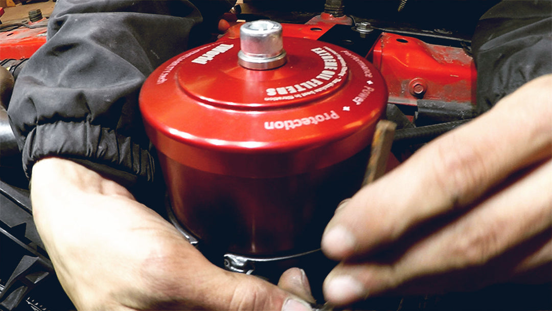
6. Assemble and Inspect the Filter Housing

- Remove the filter housing lid bolt, washer, and lid from the filter housing.
- Verify the bypass filter element is properly installed inside the filter housing with the metal ring facing up toward the lid.
- Inspect the filter housing lid O-ring and verify it is properly installed and fully seated in the groove. Replace the O-ring if it is damaged or missing.
- Inspect the lid bolt washer O-ring and verify it is properly installed and free from cuts, cracks, deformation, or other signs of damage. Replace the O-ring if necessary. Make sure the lid bolt washer chamfer faces toward the lid.
- Press down firmly on the filter element to seat the lower O-ring. If the filter element is not centered in the housing, center the lid over the element, apply downward pressure, and move the lid and filter element together until the element is centered in the housing. Maintain downward pressure while installing the washer and lid bolt.
- Tighten the filter housing lid bolt to 30 ft-lbs cold or 35 ft-lbs at operating temperature.
Do not operate the engine with a damaged, missing, or improperly installed O-ring.
7. Install the Hoses on the Filter Housing
- Apply thread sealant to the tapered pipe threads of both supplied AN06-04MS fittings where specified for this kit.
- Install the AN06-04MS from the completed pressure hose into the filter housing IN port and tighten to 120 in-lbs.
- Install the AN06-04MS from the completed return hose into the filter housing OUT port and tighten to 120 in-lbs.
- Verify the pressure hose is connected to IN and the return hose is connected to OUT.
Apply thread sealant only to verified tapered pipe threads. Do not apply thread sealant to AN flare connections, O-rings, straight-thread fittings, sealing washers, gaskets, or other sealing surfaces.
NOTE: The fittings installed in the bottom of the filter housing use tapered NPT threads and are not designed to thread completely into the housing. After the fittings are tightened to the specified torque, some fitting threads may remain visible. This is normal.
8. Mount the Assembled Filter Housing onto the Frame Bracket
- With both hoses already installed on the filter housing, feed the pressure and return hoses toward their previously identified engine connection points.
- Position the assembled filter housing onto the already-mounted ZBRCKX12 frame bracket using the filter housing side mounting bosses.
- Install the filter housing mounting hardware and tighten to 35 ft-lbs.
- Verify the housing is firmly mounted, correctly oriented, and remains accessible for future filter service.
9. Route the Hoses
- Route the pressure and return hoses along the paths established during the measurement step.
- Verify both hoses are clear of exhaust components, steering and suspension components, driveline components, sharp edges, and excessive heat sources.
- Verify there are no kinks, twists, or excessive tension in either hose.
- Leave sufficient slack for normal engine and chassis movement without placing tension on the hose or fittings.
10. Install the Return Hose at the Oil Return Port
- Remove the factory oil return port fitting using a 5/16 in. male square drive socket or suitable tool.
- Inspect the factory oil return port and verify the threads and sealing area are clean and undamaged.
- The AN06-06MS fitting is already installed on the engine end of the completed return hose coming from the filter housing OUT port. Apply thread sealant to the fitting threads where specified for this installation.
- Install the AN06-06MS end of the completed return hose into the factory oil return port and tighten to 130 in-lbs.
- Verify the return hose and fitting are oriented for proper routing without kinks, twists, excessive tension, or side load on the fitting.
11. Install the Pressure Hose at the Oil Pressure Port
Non-Van Applications
- Remove the factory oil pressure port plug.
- Inspect the factory oil pressure port and verify the threads and sealing area are clean and undamaged.
- The AN06-02MS fitting is already installed on the engine end of the completed pressure hose coming from the filter housing IN port. Apply thread sealant to the fitting threads where specified for this installation.
- Install the AN06-02MS end of the completed pressure hose into the factory oil pressure port and tighten to 110 in-lbs.
- Verify the pressure hose and fitting are oriented for proper routing without kinks, twists, excessive tension, or side load on the fitting.
E350 / E-Series / Econoline Applications
- Remove the factory oil pressure port plug.
- Inspect the factory oil pressure port and verify the threads and sealing area are clean and undamaged.
- Apply high-quality thread sealant to the NPT threads of the additional E452MF adapter. Install E452MF into the factory oil pressure port and tighten to 110 in-lbs. The fitting may be clocked to the installer’s preference for ease of hose installation.
- The AN06-02MS is already installed on the engine end of the completed pressure hose coming from the filter housing IN port. Apply thread sealant to the AN06-02MS fitting threads where specified for this installation. Install AN06-02MS directly into E452MF and tighten to 110 in-lbs.
- Verify the pressure hose and fittings are oriented for proper routing without kinks, twists, excessive tension, or side load on the fittings.
12. Secure the Hoses
- Secure the pressure and return hoses with zip ties, clamps, or appropriate existing mounting points.
- Support the hoses at regular intervals to prevent movement, chafing, abrasion, or contact with surrounding components.
- After securing the hoses, verify the routing has not created any kinks, twists, tight bends, or side loads on the fittings.
- Confirm adequate clearance remains from exhaust components, steering and suspension components, driveline components, sharp edges, and excessive heat sources.
Keep Removed Factory Parts
Important: Keep all factory plugs, fittings, hardware, and other original parts removed during installation. Place all removed factory parts together in a labeled bag and store the bag in the vehicle. In the event of an emergency, service issue, or need to return the vehicle to its factory configuration, the original plugs, fittings, hardware, and other factory components can be reinstalled.
Final Inspection
- Filter housing securely mounted
- ZBRCKX12 frame bracket securely mounted
- Frame mounting bolts torqued to 35 ft-lbs
- Filter housing side mounting hardware torqued to 35 ft-lbs
- Pressure hose connected to filter housing IN
- Return hose connected to filter housing OUT
- Pressure fitting tightened
- E350 / E-Series / Econoline only: E452MF and AN06-02MS pressure-port connection installed in the correct order
- Return fitting tightened
- Pressure hose secured
- Return hose secured
- No hose contact with sharp edges
- No hose contact with moving components
- No hose contact with driveline components
- No hose contact with exhaust components
- No hose contact with excessive heat sources
- Oil level checked
- Add oil as necessary
Initial Startup
- Add the appropriate type and quantity of engine oil to bring the engine oil level to the proper operating range before starting the engine.
- Start the engine.
- Verify oil pressure.
- Inspect the entire bypass oil filtration system for leaks, including the pressure fitting, return fitting, filter housing fittings, and hose connections.
- Verify adequate hose clearance with the engine running. Ensure the hoses are clear of moving components, driveline components, sharp edges, exhaust components, and excessive heat sources.
- Allow the engine to run for 10–15 minutes to purge air from the bypass oil filtration system and help ensure an accurate engine oil level reading.
- Turn the engine off.
- Check the engine oil level within a few minutes after shutdown to verify the correct oil level.
- Add engine oil as necessary to bring the oil level to the proper operating range.
- Perform a final inspection of the entire installation. Verify all fittings are tight, all hoses are properly secured, the filter housing is securely mounted, and there are no leaks.
The oil level may read high after the vehicle has been sitting for an extended period.
Important: Failure to add engine oil before starting the engine may result in severe engine damage or engine failure. Damage caused by operating the engine with an insufficient oil level is not covered by Insane Diesel.
Maintenance
Bypass Filter Element Replacement
This kit uses an EXTREME2 bypass filter on a diesel engine. Replace the engine bypass filter element every 15,000 miles, 250 hours, or once per year, whichever comes first.
Inspect the hoses, fittings, filter housing, pressure connection, return connection, and mounting hardware during every engine oil change and during regular vehicle maintenance. Follow the vehicle manufacturer's recommended engine oil service interval and oil specification.
Extending Oil Change Intervals
For every 100,000 miles already on the engine, Insane Diesel recommends completing at least two regular scheduled engine oil, full-flow oil filter, and bypass filter changes before extending oil or filter service intervals through oil analysis.
No matter what anyone tells you, the only way to know when you can safely run longer on the same oil is through condition-based monitoring with oil analysis. Every engine will respond differently to bypass filtration, and oil analysis provides the information needed to understand the unique trends and condition of your engine and oil.
In order to extend your oil and filter change intervals, you have to get your oil clean first. Once the oil is clean, oil and filter change intervals may be extended based on oil-analysis results. No filter cleans better than Insane Diesel's EXTREME filter.