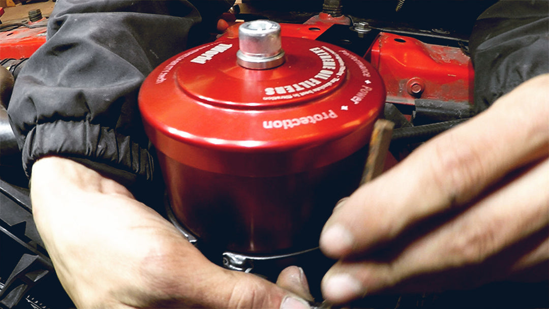



10R140 Transmission Fluid Bypass Filter Kit Installation Guide
Insane Diesel Installation Guide
10R140 TRANSMISSION BYPASS FLUID FILTER KIT INSTALLATION GUIDE (2020–PRESENT)
Application Notice
This guide applies to Ford 2020–Present vehicles equipped with the 10R140 transmission, including compatible Ford Super Duty applications.
- Ford F-250 Super Duty
- Ford F-350 Super Duty
- Ford F-450 Super Duty
- Ford F-550 Super Duty
- Ford 7.3L gas “Godzilla”
- Ford 6.8L gas “Mini Godzilla” Super Duty
Verify the vehicle year, transmission model, transmission pan configuration, pressure port location, return port location, available mounting space, and hose routing path before installation.
Professional Installation Recommended
Insane Diesel recommends this transmission bypass filtration kit be installed by a qualified mechanic. The installer must verify transmission port locations, confirm fitting thread compatibility, choose a safe mounting location, and route hoses clear of moving components, driveline components, sharp edges, exhaust components, and excessive heat sources.
Installation Video
Ford 10R140 Transmission Bypass Fluid Filter Kit Installation Video
Use the installation video alongside this written guide. Always verify the correct 10R140 pressure port, return port option, hose routing, and mounting location on the specific vehicle being installed.
Installation Overview
Do not open labeled parts bags until instructed. Keep all labeled parts bags until installation is complete.
| Specification | Details |
|---|---|
| Vehicle / Transmission | Ford 2020–Present applications equipped with the 10R140 transmission |
| Application Range | 2020–Present |
| Mounting Style | Universal / frame mount using supplied ZBRCKX12 mounting bracket. Frame installations use supplied 3/8 in. self-threading frame mounting bolts. |
| Estimated Install Time | 3–5 hours, depending on pan configuration and mounting location |
| Skill Level | Difficult / professional installation recommended |
| Pressure Port | 10orifice 10 mm straight-thread restrictor with D10 sealing washer and AN06-02MS90 NPT pressure fitting |
| Return Port Options | Stock oil return pan using AN06-18MMx1.5 and AN06-06FJ90, or aftermarket Banks/PPE transmission pan return using AN06-02MS90 |
| Supplied Hose | 8 ft LW06BK continuous hose. Measure and cut based on the final filter-housing location and complete pressure and return routing. |
| Transmission Fluid | Verify transmission fluid level after installation and add approved transmission fluid as necessary. |
Engineered to Protect the Ford 10R140 Transmission Where Factory Filtration Ends
The Ford 10R140 10-speed heavy-duty automatic transmission relies on extremely precise hydraulic control through shift solenoids, clutch-control valves, and a highly sensitive valve body. Over time, microscopic wear debris and fine particulate contamination circulating in the transmission fluid can interfere with these components, contributing to harsh or erratic shifts, delayed engagement, and accelerated internal wear.
The Insane Diesel 10R140 Bypass Transmission Fluid Filter Kit is engineered specifically for 2020–Present Ford Super Duty trucks and other gas engines equipped with the 10R140 transmission. It provides continuous fine-particle filtration beyond what the factory system is designed to capture, helping reduce contamination load and support long-term transmission reliability under heavy towing, high load, and extended service conditions.
Before You Begin
- Verify all supplied kit components are present before beginning installation.
- Verify the vehicle is equipped with a compatible 10R140 transmission.
- Confirm which fluid return option will be used before cutting hose or installing fittings.
- Verify the pressure port location, return port location, transmission pan configuration, hose routing, and mounting location.
- Verify the bypass filter housing contains the filter element, lid O-ring, lid bolt washer O-ring, and all required sealing components.
- Determine the complete pressure and return hose routing before cutting the supplied continuous hose.
- Read the entire installation guide before beginning.
- Review all reference photos and watch the installation reference video.
- Park the vehicle on a level surface and allow the drivetrain to cool before servicing transmission fluid components.
Required Tools
- Basic mechanic tool set.
- Inch-pound torque wrench.
- Foot-pound torque wrench.
- Crow's foot wrenches.
- Hose cutting tool or equivalent.
- Drill for Frame Mount installation.
- Center punch.
- Small pilot drill bit.
- 21/64 in. drill bit for the supplied 3/8 in. self-threading frame mounting bolts.
- Appropriate mounting tools and hardware if a non-frame mounting surface is selected.
- Rivnut installation tool if the selected non-frame mounting method uses rivnuts.
- High-quality thread sealant for verified NPT fittings.
- Blue medium-strength threadlocker, such as Loctite® 242 or equivalent, for mounting bolts where applicable.
- Zip ties or clamps for hose routing and securing.
Kit Contents
NOTE: Fittings that use tapered NPT threads are not designed to thread completely into the component. Apply the specified thread sealant and tighten the fitting to the specified torque. Some fitting threads may remain visible after installation; this is normal.
Important Torque Note
Make sure to follow the torque specs for each fitting. Overtightening components may cause component failure that will not be covered by Insane Diesel. When transmission service information specifies a different torque value, follow the vehicle-specific service information. The female hose socket-to-fitting-barb assembly does not use a torque specification. Tighten the fitting barb until it meets the hose socket.
Parts Gallery
Do not open labeled parts bags until instructed. Keep all labeled parts bags until installation is complete.
Use the part numbers below to identify the supplied components. The black HX2SHBK housing is shown first as the gallery reference; other housing colors and the bundled D10 washer and GX12 sealing components are not shown separately. Return-port parts depend on the selected transmission pan configuration.


| Part Number | Description | Qty | Applies To | Torque Specs |
|---|---|---|---|---|
| HX2SHBK / HX2SHBLU / HX2SHRED | EXTREME2 bypass filter housing, color selected at purchase | 1 | All kits. Color does not affect installation. | Filter housing lid: 30 ft-lbs cold / 35 ft-lbs operating temperature |
| EX2ME / GX12 | EXTREME2 filter element with O-rings | 1 | All kits | N/A |
| AN06-04MS90 | NPT In/Out fittings | 2 | Filter housing inlet and outlet | 120 in-lbs + high-quality thread sealant on the 1/4 NPT connection |
| ZBRCKX12 | Universal / frame mounting bracket with supplied 3/8 in. self-threading frame mounting bolts | 1 | Universal / frame mount | Frame mounting bolts: 35 ft-lbs; filter housing side mounting bosses: 35 ft-lbs |
| LW06BK | 8 ft continuous hose to be measured and cut based on final pressure and return routing | 1 | Pressure and return hose routing | N/A |
| 10orifice / D10 / AN06-02MS90 | Pressure port fitting system with 10 mm straight-thread restrictor, 1 mm port, sealing washer, and NPT pressure fitting | 1 | Pressure Port | 10orifice: 60 in-lbs, straight-thread/sealing-washer connection, no NPT thread sealant; D10: no thread sealant; AN06-02MS90: 110 in-lbs + high-quality thread sealant on the 1/8 NPT connection |
| AN06-18MMx1.5 / AN06-06FJ90 | Stock oil return pan return fitting system | 1 option | Stock Oil Return Pan | AN06-18MMx1.5: 60 in-lbs, metric straight thread with O-ring sealing component, no NPT thread sealant; AN06-06FJ90: tighten to 60 in-lbs, loosen, then re-tighten to 110 in-lbs |
| AN06-02MS90 | NPT aftermarket Banks or PPE transmission pan oil return fitting | 1 option | Aftermarket Banks or PPE Transmission Pan Oil Return | 110 in-lbs + high-quality thread sealant on the 1/8 NPT connection |
Fluid Return Options
- Stock Transmission Pan Return: use AN06-18MMx1.5 with AN06-06FJ90 and the supplied 8 ft LW06BK hose.
- Aftermarket Banks or PPE Transmission Pan Oil Return: compatible with Banks 35165-B or PPE Transmission Pan Part #328053510, purchased separately. Use AN06-02MS90 and the supplied 8 ft LW06BK hose.
Custom Installation and Mounting Details
Important Installation Info
- There is no single mounting location that applies to every compatible Ford 10R140 vehicle. Choose a secure, serviceable mounting location that allows safe hose routing and future filter service.
- Verify the pressure port, return port option, hose routing, and selected mounting location before cutting hose or tightening final hardware.
- Installation / assembly is recommended to be performed by a professional mechanic.
Mounting Location Selection
- Select a suitable mounting location that is structurally secure and as close to the transmission pressure and return locations as practical.
- Before drilling or mounting the bracket, confirm there is adequate hose length to route between the filter housing, pressure source, and return location.
- Verify adequate clearance for the filter housing, pressure and return hoses, suspension and steering components, driveline components, exhaust components, wiring, sharp edges, moving components, and excessive heat sources.
- Confirm the filter housing can be serviced in the selected location without interference. The filter housing lid must be removable for future filter service.
- Inspect both sides of the selected mounting surface before drilling to ensure no wiring, brake lines, fuel lines, hoses, or other components will be damaged.
- Do not mount the filter housing where it will contact moving components, sharp edges, or excessive heat sources.
Installation Procedure
1. Find the Filter Housing Location
This kit uses the supplied ZBRCKX12 universal/frame-mount bracket. Select a secure, serviceable mounting location before drilling or cutting hose.
- Select a suitable mounting location that allows safe hose routing between the filter housing, transmission pressure port, and selected transmission return port.
- Before drilling or mounting the bracket, confirm the supplied 8 ft LW06BK continuous hose is sufficient for both completed hose routes.
- Verify the mounting location provides adequate structure for the mounting bracket and filter housing.
- Verify adequate clearance for the filter housing, pressure and return hoses, suspension and steering components, driveline components, exhaust components, wiring, sharp edges, moving components, and excessive heat sources.
- Confirm the filter housing can be serviced in the selected location without interference. The filter housing lid must be removable for future filter service.
- Inspect both sides of the selected mounting surface before drilling.
- Do not mount the filter housing where it will contact moving components, sharp edges, or excessive heat sources.
2. Find the Transmission Pressure Location

- Locate the 10R140 transmission pressure port.
- Verify the exact port location before removing any factory pressure plug or pressure-port component.
- Verify the supplied pressure components are present: 10orifice, D10, and AN06-02MS90.
3. Find the Transmission Return Location

Choose the return configuration before building the return hose:
- Stock Oil Return Pan: AN06-18MMx1.5 with AN06-06FJ90.
- Aftermarket Banks or PPE Transmission Pan: compatible with Banks 35165-B or PPE Transmission Pan Part #328053510, purchased separately, using AN06-02MS90.
- Verify the exact return-port location and transmission pan configuration before removing any factory component.
- Confirm the selected return fitting matches the port thread and sealing style.
4. Measure and Build the Hoses
Before proceeding with Step 4, watch The Complete Insane Diesel Hose & Fitting Installation Guide below so you are familiar with the correct reusable hose fitting assembly procedure.
The kit includes 8 ft of LW06BK continuous hose. Verify the complete pressure and return routing before making either cut.
Incorrect Hose Assembly Examples


Correct Hose Assembly Examples


The Complete Insane Diesel Hose & Fitting Installation Guide
- Determine the complete routing between the planned filter housing location, pressure source, and return.
- Starting at one end, route the hose from the planned filter housing location to the pressure source and mark the pressure-hose cut location.
- Starting from the opposite end, route the hose from the planned filter housing location to the return and mark the return-hose cut location.
- Verify the cut marks do not overlap. If hose remains between the marks, cut between the marks so both can remain slightly longer.
- Follow a safe and serviceable routing path.
- Avoid moving components, steering and suspension components, sharp edges, rotating assemblies, exhaust components, and excessive heat sources.
- Leave sufficient slack for normal engine and chassis movement.
- Verify the complete routing before cutting the hose.
- Cut the hose at the verified cut locations.
- Cut each hose squarely and cleanly. Ensure each cut is free from frayed braid, burrs, or deformation.
- Remove the socket from the fitting assembly. Insert the hose into the fitting socket until the rubber can be seen touching the bottom of the female threads of the socket. Make sure ALL of the nylon braided covering is fully inside the socket, with no frays or nylon bunching.
- Lubricate the fitting barb with clean oil and thread the barb into the fitting socket until the barb touches the socket. Ensure while threading the barb into the socket that it is not pushing the hose out of the socket.
- Assemble the reusable hose ends as shown in The Complete Insane Diesel Hose & Fitting Installation Guide. The female hose socket-to-fitting-barb assembly does not use a torque specification. Tighten the fitting barb until it meets the hose socket.
-
Pressure Hose: Install one AN06-04MS90 on the filter-housing IN end and one AN06-02MS90 on the transmission pressure-port end.
AN06-04MS90 — Pressure Hose — AN06-02MS90 -
Stock-Pan Return Hose: Install one AN06-04MS90 on the filter-housing OUT end and one AN06-06FJ90 on the transmission return-port end. The AN06-06FJ90 connects to AN06-18MMx1.5 in Step 11A.
AN06-04MS90 — Return Hose — AN06-06FJ90 -
Aftermarket Banks/PPE Pan Return Hose: Install one AN06-04MS90 on the filter-housing OUT end and one AN06-02MS90 on the transmission-pan return end.
AN06-04MS90 — Return Hose — AN06-02MS90 - Before moving on, verify the completed pressure and return hose assemblies match the selected return configuration and are correctly identified.
- Verify both completed hose assemblies are free from kinks and twists.
Important: Do not allow the hose to become twisted during installation. Verify each hose follows a smooth routing path with large-radius bends and does not place side loads on the fittings.
5. Install the ZBRCKX12 Mounting Bracket
Mounting Note: For a frame installation, use the supplied 3/8 in. self-threading frame mounting bolts. If a non-frame mounting surface is selected, the installer must use an appropriate mounting method for that surface. Rivnuts and bolts may be used where appropriate.
- Position the supplied ZBRCKX12 bracket against the selected mounting surface and use it as a template to mark the mounting holes.
- Inspect both sides of the mounting surface before drilling. Make sure the drilling location is clear of brake lines, fuel lines, wiring harnesses, body panels, hoses, and other components that could be damaged.
- Use a center punch to mark the center of each mounting location.
- Drill a small pilot hole at each marked location.
- For a frame installation using the supplied 3/8 in. self-threading frame mounting bolts, enlarge each pilot hole using a 21/64 in. drill bit.
- Remove all burrs, metal chips, and shavings from the drilled holes and work area.
- Apply blue medium-strength threadlocker, such as Loctite® 242 or equivalent, to the supplied frame mounting bolt threads.
- Install the ZBRCKX12 bracket using the supplied 3/8 in. self-threading frame mounting bolts.
- Tighten the self-threading frame mounting bolts to 35 ft-lbs.
- Verify the bracket is securely mounted and maintains adequate clearance from surrounding vehicle components.
6. Assemble and Inspect the Filter Housing

- Remove the filter housing lid bolt, washer, and lid from the filter housing.
- Verify the bypass filter element is properly installed inside the filter housing with the metal ring facing up toward the lid.
- Inspect the filter housing lid O-ring and verify it is properly installed and fully seated in the groove. Replace the O-ring if it is damaged or missing.
- Inspect the lid bolt washer O-ring and verify it is properly installed and free from cuts, cracks, deformation, or other signs of damage. Replace the O-ring if necessary. Make sure the lid bolt washer chamfer faces toward the lid.
- Press down firmly on the filter element to seat the lower O-ring. If the filter element is not centered in the housing, center the lid over the element, apply downward pressure, and move the lid and filter element together until the element is centered in the housing. Maintain downward pressure while installing the washer and lid bolt.
- Tighten the filter housing lid bolt to 30 ft-lbs cold or 35 ft-lbs at operating temperature.
Do not operate the vehicle with a damaged, missing, or improperly installed O-ring.
7. Install the Hoses on the Filter Housing
- Apply high-quality thread sealant to the 1/4 NPT threads of both AN06-04MS90 fittings already installed on the filter-housing ends of the completed hose assemblies.
- Install the AN06-04MS90 from the pressure hose into the filter housing IN port and tighten the 1/4 NPT connection to 120 in-lbs.
- Install the AN06-04MS90 from the return hose into the filter housing OUT port and tighten the 1/4 NPT connection to 120 in-lbs.
- Verify the pressure hose is connected to the IN side and the return hose is connected to the OUT side before mounting the housing.
AN06-04MS90 is a 1/4 NPT fitting and requires high-quality thread sealant. Do not apply thread sealant to AN flare connections, O-rings, sealing washers, gaskets, straight-thread sealing connections, or other sealing surfaces.
NOTE: The fittings installed in the bottom of the filter housing use tapered NPT threads and are not designed to thread completely into the housing. After the fittings are tightened to the specified torque, some fitting threads may remain visible. This is normal.
8. Mount the Assembled Filter Housing onto the Installed Bracket
- Position the EXTREME2 filter housing with both hoses attached onto the installed ZBRCKX12 bracket using the side mounting bosses on the filter housing.
- Orient the filter housing to provide smooth hose routing and adequate clearance for future filter servicing.
- Apply blue medium-strength threadlocker or equivalent to the filter housing mounting bolt threads.
- Tighten the filter housing side mounting bolts to 35 ft-lbs.
- Verify the bracket is securely fastened, the filter housing is firmly mounted, and the housing lid can be removed for future service.
9. Route the Hoses
- Route the pressure and return hoses along the paths established during the measurement step.
- Verify both hoses are clear of exhaust components, steering and suspension components, driveline components, sharp edges, and excessive heat sources.
- Verify there are no kinks, twists, or excessive tension in either hose.
- Leave sufficient slack for normal transmission, drivetrain, and chassis movement without placing tension on the hose or fittings.
10. Install the Transmission Pressure Port Fitting and Connect the Pressure Hose
- Locate the confirmed 10R140 pressure port and remove the factory pressure plug.
- Inspect the supplied 10orifice, D10, and the AN06-02MS90 already installed on the completed pressure hose.
- Install the D10 sealing washer onto the 10orifice restrictor. Verify the sealing washer is clean, undamaged, and properly positioned. Do not apply thread sealant to the D10 washer or the 10 mm straight-thread sealing connection.
- Install the 10orifice into the confirmed transmission pressure port and tighten to 60 in-lbs.
- Apply high-quality thread sealant to the 1/8 NPT threads of the AN06-02MS90 pressure-hose fitting.
- Install the AN06-02MS90 pressure-hose end into the 10orifice and tighten to 110 in-lbs. Hold the 10orifice with a backup wrench while tightening AN06-02MS90 so the 60 in-lb straight-thread restrictor does not rotate or become over-tightened.
- Verify the pressure fitting, restrictor, and pressure hose do not contact surrounding components after final orientation.
Important: The supplied 10 mm straight-thread 10orifice restrictor uses the D10 sealing washer and tightens to 60 in-lbs. Do not apply thread sealant to the straight-thread restrictor or sealing washer. AN06-02MS90 is a 1/8 NPT fitting and requires high-quality thread sealant; tighten it to 110 in-lbs. Do not omit the restrictor.
11. Install the Transmission Return Port/Fitting and Connect the Return Hose
11A. Stock Transmission Pan Return
- Confirm the vehicle will use the stock transmission pan return option.
- Locate the confirmed stock transmission pan return port and remove the factory return plug.
- Inspect AN06-18MMx1.5 and the AN06-06FJ90 already installed on the completed return hose.
- Verify the O-ring sealing component on AN06-18MMx1.5 is properly installed, fully seated, clean, and free from cuts, cracks, deformation, or other damage. Do not apply NPT thread sealant to this metric straight-thread/O-ring-sealed connection.
- Install AN06-18MMx1.5 and tighten to 60 in-lbs.
- Using a backup wrench to hold AN06-18MMx1.5 and prevent it from rotating or being over-tightened, connect the return-hose AN06-06FJ90.
- Tighten AN06-06FJ90 to 60 in-lbs, loosen, then re-tighten to a final torque of 110 in-lbs.
- Verify the return fitting and hose do not contact surrounding components after final orientation.
Important: AN06-18MMx1.5 is a metric straight-thread fitting that uses an O-ring sealing component. Tighten it to 60 in-lbs. Do not apply NPT thread sealant to the metric straight-thread/O-ring-sealed connection or the AN06-06FJ90 AN flare connection.
11B. Aftermarket Banks or PPE Transmission Pan
- Confirm the installation uses a compatible aftermarket pan, such as Banks 35165-B or PPE Transmission Pan Part #328053510, purchased separately.
- Install the aftermarket pan according to the pan manufacturer instructions and vehicle service information before completing the return connection.
- Locate the transmission-pan return port and remove any factory plug or component as required.
- Inspect the AN06-02MS90 already installed on the completed return hose.
- Apply high-quality thread sealant to the 1/8 NPT threads of the AN06-02MS90 fitting.
- Install the AN06-02MS90 return-hose end and tighten to 110 in-lbs.
- Verify the return fitting and hose do not contact surrounding components after final orientation.
AN06-02MS90 is a 1/8 NPT fitting and requires high-quality thread sealant. Tighten to 110 in-lbs.
12. Secure the Hoses
- Secure the pressure and return hoses with zip ties, clamps, or appropriate existing mounting points.
- Support the hoses at regular intervals to prevent movement, chafing, abrasion, or contact with surrounding components.
- After securing the hoses, verify the routing has not created any kinks, twists, tight bends, or side loads on the fittings.
- Confirm adequate clearance remains from exhaust components, steering and suspension components, driveline components, sharp edges, and excessive heat sources.
Keep Removed Factory Components in the Vehicle
Important: After installation is complete, place all factory components removed during installation and not reinstalled into a labeled bag and keep the bag in the vehicle. This includes factory transmission pressure-port and return-port plugs or components, sealing pieces, and any other original components not reinstalled.
Keeping the original components with the vehicle allows the factory transmission-fluid connections to be restored if an emergency or service situation requires the bypass system to be temporarily removed or bypassed.
Final Inspection
- Filter housing securely mounted
- Mounting bracket securely mounted
- 10orifice installed with D10, no NPT sealant, and tightened to 60 in-lbs
- Pressure-side AN06-02MS90 installed with thread sealant and tightened to 110 in-lbs
- Selected return port fitting installed
- Stock-pan AN06-18MMx1.5 O-ring sealing component inspected and fitting installed without NPT sealant and tightened to 60 in-lbs.
- AN06-06FJ90 tightened to 60 in-lbs, loosened, then re-tightened to 110 in-lbs.
- Aftermarket-pan AN06-02MS90 installed with thread sealant and tightened to 110 in-lbs.
- Pressure hose connected to filter housing IN
- Return hose connected to filter housing OUT
- Pressure hose secured
- Return hose secured
- No hose contact with sharp edges
- No hose contact with moving components
- No hose contact with driveline components
- No hose contact with excessive heat sources
- Transmission fluid level checked
- Add transmission fluid as necessary
Initial Startup
- Add the appropriate type and quantity of approved transmission fluid as required to bring the transmission fluid level to the proper operating range before operating the vehicle.
- Start the engine.
- Verify transmission fluid pressure and confirm fluid circulation through the bypass filtration system.
- Inspect the entire transmission bypass filtration system for leaks.
- Verify adequate hose clearance with the engine running. Ensure the hoses are clear of moving components, driveline components, sharp edges, and excessive heat sources.
- Allow the vehicle to reach the transmission fluid temperature range required by the vehicle service procedure for accurate fluid level verification.
- Cycle the transmission through the required gear ranges according to the vehicle service procedure.
- Check the transmission fluid level using the correct vehicle-specific procedure.
- Add approved transmission fluid as necessary to bring the fluid level to the proper operating range.
- Perform a final inspection of the entire installation. Verify all fittings are tight, all hoses are properly secured, the filter housing is securely mounted, and there are no leaks.
Important: Failure to add the correct transmission fluid before operating the vehicle may result in severe transmission damage or transmission failure. Damage caused by operating the transmission with an insufficient fluid level is not covered by Insane Diesel.
Maintenance
Bypass Filter Element Replacement
Replace the transmission bypass filter element at the vehicle or transmission manufacturer's recommended transmission service interval or once per year, whichever comes first.
During every transmission service, inspect the transmission fluid level, hoses, fittings, filter housing, pressure and return connections, selected transmission pan return configuration, and mounting hardware.